Reciprocal space and the reciprocal lattice
By analogy with our definition of a one-dimensional Fourier transform, the three-dimensional Fourier transform can be defined as:

The only differences between this and the one-dimensional equivalent are that F and f are functions of three-dimensional vectors K and r respectively, and the product in the exponential is now a vector dot product. (Again, I am not worrying about minus signs and other factors in the exponential.) When we were thinking about how to perform a one-dimensional transform on a one-dimensional grating function, we used a diagram like this:
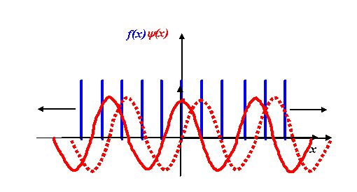
We multiplied our grating function by a stationary corkscrew function, and then integrated the resulting product over the entire extent of x. In two dimensions, the corkscrew function eiK.r is just a two-dimensional wave, as we described earlier.
Consider the distribution of atoms shown in the next diagram:
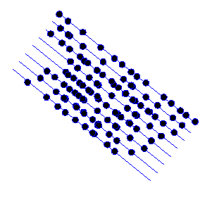
I’ve deliberately made the atom positions random, except for the fact that they are all roughly arranged on the blue lines.
Now when we take the Fourier transform of this two-dimensional distribution, we multiply the object function by all possible two-dimensional corkscrew functions, each with a different two-component K-vector. Here are some examples, for different K-vectors, coloured brown:
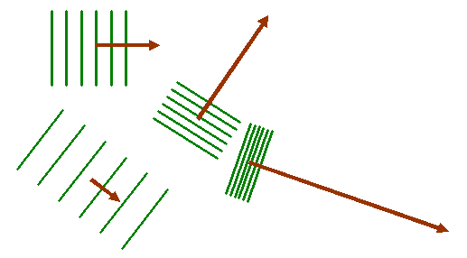
Remember that the green lines are where the corkscrew function has a particular phase, say zero. At zero phase, the real (cosine) part of the corkscrew function has its maximum value. At points on lines between the green lines, the corkscrew function has a maximum negative value (cos π = -1). Lets imagine superposing one of these two-dimensional waves upon our object function, as shown below:
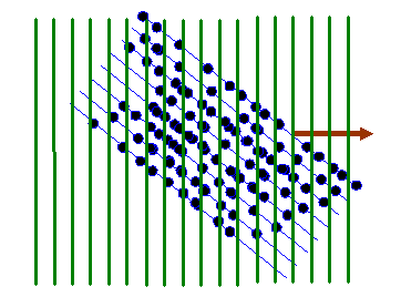
In the next diagram, I draw red lines between the green lines: on these red lines the corkscrew function has a negative value. When we form the product between the atom distribution and the corkscrew function, atoms that lie on a green line give a positive resultant (coloured dark in the diagram below). Atoms that arrive on the red lines give a negative resultant (coloured red below). Atoms that lie between these positive and negative lines give a small resultant (coloured grey below).
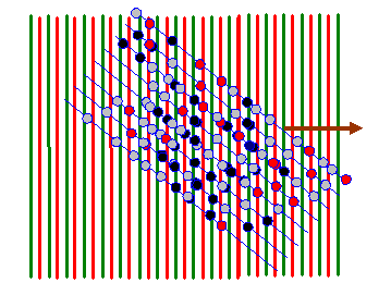
For nearly all orientations and periodicities of the two-dimensional corkscrew function (nearly all values of the vector K in eiK.r) there are as many positive (dark) atoms as negative (red) atoms. However, like in the one-dimensional example we discussed before, when the green lines are in synchrony with the blue lines (the only clear periodicity in this array of atoms) then the integral of f(r) times eiK.r is very large. Two example K vectors that satisfy this condition are shown below:
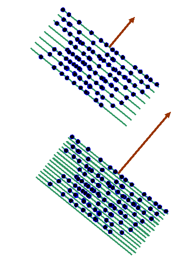
In reciprocal space (or ‘k-space’), the two brown vectors correspond to positions plotted from the origin where F(K) is very large, like this:
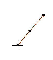
The cross is the origin of 2D reciprocal space. The black dots are where F(K) has a very large value, at the positions of brown K-vectors in the previous diagram. In fact, corkscrew functions pointing in the opposite direction to these K-vectors will also give large Fourier integrals. Indeed, any multiple length of the brown vector also gives a peak. In the next diagram, we draw the main features of reciprocal space for this partly-ordered structure.
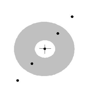
Spots (which in a real electron diffraction pattern would appear as bright points of light on the phosphor screen) represent prevalent periodicities in the object. I’ve drawn a grey circle on this picture to suggest a ‘diffuse ring’: it would be wrong to suggest that from such an object, disordered in all but one direction, there would be no scattering at all at K-vectors that do not correspond to the periodic planes. There is in fact weak diffraction, around several rings in reciprocal space (only one of which is drawn) caused by prevalent average separations of the atoms.
For an entirely crystalline object (and most materials are crystalline) then it stands to reason that there is an array of sharp peaks in reciprocal space. Consider the following two-dimensional crystal:
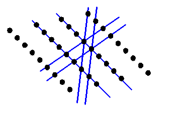
Reciprocal space will now consist of only a series of points. The points will be at K-vectors which are perpendicular to the blue lines (planes in three-dimensions) and with lengths which are multiples of 1/(the distance between the planes). If you are new to reciprocal space, then this is the point where most people’s brains reach overload. In the next diagram, I draw the reciprocal vectors corresponding to the blue lines in brown.
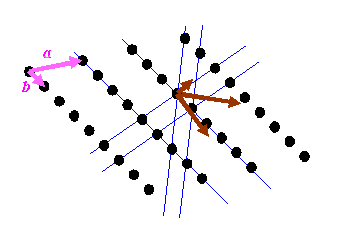
I have also drawn two pink vectors, labelled a and b: these two vectors can be used to generate the real-space distribution of atoms. The position of any of the atoms can be described by r = na + mb, where n and m are integers. Crystallography starts with these pink vectors, and then, rather mysteriously, defines the reciprocal (brown) vectors, or at least a subset of the brown vectors from which can be generated all reciprocal lattice points.
It is important to understand that the brown vectors do not point in the same direction as the pink vectors unless the pink vectors are perpendicular to one another. Can you believe the right hand lattice is the reciprocal of the left hand lattice in the diagram below?
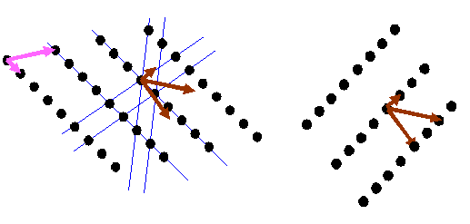
If you understand this fully, then you have understood one of the (several, but rather abstract) essential concepts in crystallography. I think the most general way of thinking about reciprocal space is as the Fourier transform of real space, which is the way I have described it on this page. This model can easily be extended to understand diffraction from thin and distorted crystals, as often encountered in electron microscopy. But this is not the way crystallographers generally think (or teach) the subject.
Most textbooks state a relationship between the two lattices above in terms of vector algebra. For the sake of completeness, let’s derive this in simple steps, because it is important. Consider a bit of the real space distribution of atomic positions:
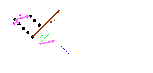
We know that the length of a*, which the reciprocal vector corresponding to a, must have a length of 1/d, where d is the spacing between the blue lines, marked as green in the diagram above. It must also be pointing in direction perpendicular to the blue planes. So we have to do two things: work out a way of constructing a unit vector (a vector of length 1) pointing in the direction of a* (call this a’), and work out a way of deriving the distance d.
The first step is easiest if we can imagine a third real-space vector, called c, which sticking into the paper (computer screen). By definition, the cross product of b with c is a vector pointing in the direction of a*: remember, the cross product, which we’ll write as bxc, is a vector at right angles to both b and c. To get a unit vector, we must divide whatever we end up with by its length. So that means that

To work out d, we can take the dot product of a with a’: that is, we pick out the component of a lying in the a’ direction. We multiply a’ by 1/d, to get

so that finally

There are similar expressions for b* and c*. The triple product a.bxc is the volume of the parallelepiped of sides a, b and c, which is the volume of the unit cell in the real space.
This relationship is tricky to think of three-dimensional space. In general, c does not point perpendicularly into the paper (computer screen) but can be at any angle. In that case, the blue Bragg planes do not cut the paper (computer screen) at right angles, and so neither a* nor the green line d are in the plane of the paper. The above relationship still holds true. To get of picture of this in mind’s eye, think our three-dimensional corkscrew made of sheets of cardboard:
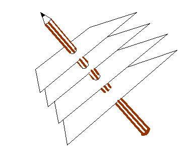
You have to orientate this, altering also the separation of the sheets, until the sheets line up with a series of planes of atoms. You can try doing this if you have access to a ball-and-spoke model of a crystal. The brown pencil, of length 1/d, is then pointing from the origin of reciprocal space to some point in reciprocal space. There are many planes which satisfy this condition, each accounting for one point in reciprocal space. Like the atom positions in real space, all the points in reciprocal space can be generated from just three of these k-vector (a*, b* and c*). Clearly, if a* is the brown pencil in the diagram above, then b and c are bound to lie in the plane of the sheet of cardboard, whatever their direction or length. That is why the cross product, bxc can be used to generate a*. Reciprocal vectors are perpendicular to planes of atoms.


Copyright J M Rodenburg
| 
