The diffraction grating
If we have loaded a crystalline specimen into the
electron microscope and we press the ‘diffraction’
button, then what we see is grid of bright spots. People
often say this grid (which is usually incomplete – only a
few bright spots are lit up, unless the specimen has been
accurately aligned) is ‘like a diffraction grating
pattern’. It is like a diffraction grating pattern,
although in fact, unlike the pattern we would obtain from
an optical diffraction grating, the behaviour of an
electron diffraction pattern is made more complicated by
the thickness of the object and multiple (dynamical)
scattering.
I still think it is worth rehearsing the behaviour of
a conventional (optical) diffraction grating before we
try to discuss three-dimensional electron diffraction
effects. There three reasons for this: 1) diffraction
from periodic (crystalline) arrays of atoms is absolutely
key in electron imaging, and so we may as well spend some
time understanding fully the simplest example of
diffraction from a one-dimensional periodic object; 2)
the diffraction grating can give us a qualitative insight
into the nature of the convolution theorem; 3) the
diffraction grating can illuminate, in a physical way,
the difference between the Fourier integral and the
discrete Fourier transform.
Lets just recall how we constructed our sinc
function. We took the Fourier transform of a top hat
function which looked like this
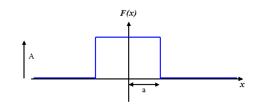
in order to find the amplitude of the Fraunhofer
diffraction pattern. Now lets think about taking the
Fourier transform (that is, forming the Fraunhofer
diffraction pattern) of not a continuous top-hat
function, but one made up of a series of spikes, like a
hair comb. Physically, we would construct this from a
series of equally-spaced slits – a diffraction grating.
The functional form of the exit wave emerging immediately
behind the grating looks like this:
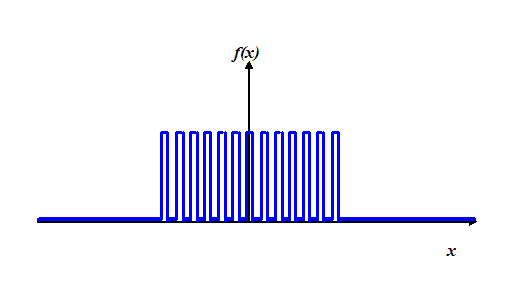
To begin with, let’s assume each spike in this
function is infinitesimally narrow. We can use our
mechanical Fourier transform machine to
calculate what the diffracted amplitude will look like a
very long way from the grating, as a function of angle.
I want to think about this by considering more and more
slits, starting off with just two slits. In other words,
a series of functions that looks like this:
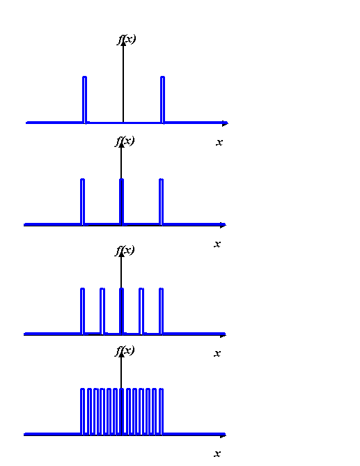
In the complex plane, we will have wave value vectors
for these four examples that, at some small scattering
angle, add like this:
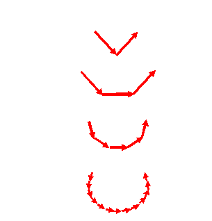
At we increase the scattering angle, the vectors
rotate, changing the resultant vector, which, as before,
we draw between the two ends of chain of wave vectors.
Of course, in the limit of infinitely many tiny slits, we
tend towards the chain being a continuous line, like in
our calculation of the sinc function. At
the opposite limit of just two slits, we just have our Young’s slits amplitude distribution. It
doesn’t take much imagination to think through what will
happen to the resultant vectors, as a function of
scattering angle, between these two extremes.
Qualitatively, for an increasing number of slits, the
diffracted amplitude looks like this:
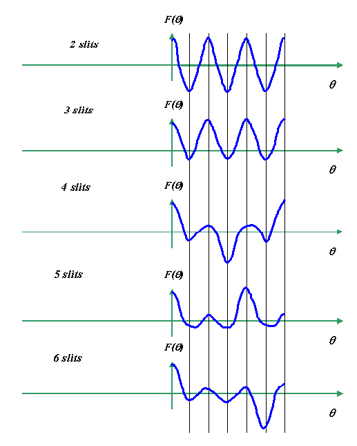
These diagrams are not quantitatively accurate (I did
them using the mouse and the curve ‘autoshape’, so they
are a bit wonky – the crossing points and magnitudes are
purely qualitative). What’s happening is that as we
increase the number of slits, then the ‘snake’ of added component vectors writhes
around in a tighter and tighter bundle. Every so often,
the bundle straightens out into a large magnitude. For
two slits, the first maximum magnitude occurs on the
first vertical line (above), and is purely negative. For
three slits, it occurs on the second line, and is
positive. For four slits, the first maximum magnitude
occurs on the third line, and is negative, and so on and
so forth.
Aside: We might infer from these diagrams
that the complex value of a diffraction pattern from an array of
atoms changes very dramatically depending on whether we have
an even or an odd number of atoms across the width of a
crystallite. Well, that's not quite true. The way we've
constructed our distribution of slits (atoms) here means that
an even number of slits appear shifted (by half their spacing)
along the x-axis relative to the case of an odd number of
slits. This shift is really responsible for the positive and
negative peaks in the amplitude, because a shift introduces a
phase ramp across the Fourier transform. Because here we have arranged to keep the result
purely real (by keeping the slits symmetric about the origin), then
this phase change results in a π shift in some of the even-slit
diffraction peaks. Don't worry about it... :end of aside
The pattern repeats itself at equal intervals.
I haven’t drawn negative values of θ: all these
graphs are symmetric about the origin. As the number of
slits is increased, the big peaks migrate to larger
values of θ, until eventually we are just left with
a single peak at the origin in the shape of a sinc
function. At this stage, our comb of infinitesimally
tiny gaps has blurred into just a top hat function.
Physically, we are adding up an infinite number of
secondary waves, according to Huygen’s
Principle.
Most textbooks derive the intensity
distribution of these peaks, which of course will miss
out the subtleties of the change of sign of the
amplitude. The intensities, which is of course is what
we see when we do a diffraction experiment, look (very
roughly) like this:
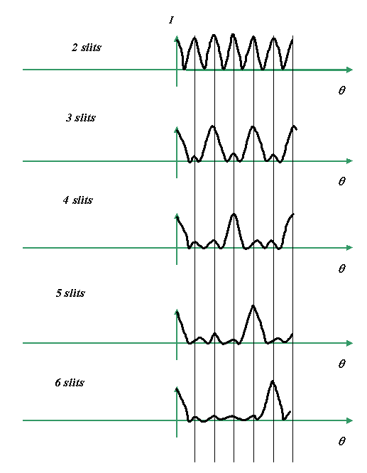
Looking the intensity, the pattern of the evolution
of the grating pattern becomes a little bit clearer. The
first peak from an N-slit grating occurs at
δθ(N-1), where δθ is the angle of
the first maximum in a Young’s slits experiment, where
the separation of the slits is the width of the grating.
This is usually taught as occurring when there is an
integral number of wavelengths in the path difference
between adjacent slits. Obviously, when this occurs, all
the little contributing wave vectors come back into phase
with another, and so the ‘writhing snake’, which produces
all the subsidiary peaks between the main diffraction
maxima, suddenly straightens out.
We can think of this another way. Instead of having
a fixed width of the whole grating, and then adding more
and more slits each spaced by a smaller distance, we
could think of adding more and more slits each separated by
the same distance. In this case, the scattering angle of
the diffraction peaks remains constant, but the width of
the peaks decrease as N, the number of slits, is
increased. This is much more like scattering from a
periodic array of atoms. The total width of a given
crystallite determines the clarity (or sharpness) of a
diffraction peak (indeed, this fact can be used to
estimate crystallite size in both X-ray and electron
diffraction, via the Scherrer formula). In optical
spectroscopy, the chromatic resolution of a diffraction
grating is proportional to the number of slits for the
same reason. In fact, in any practical set up (optical,
X-ray or electron) the actual width of diffraction peaks
is often determined by the angular size of the
illuminating wave field: in other words, its spatial
coherence.


Copyright J M Rodenburg
|

