Bragg’s Law
In my flippant introduction to crystallography and diffraction theory, I suggested that scattering from a single atom could be represented by a phase thread passing through the eye of needle, like this:
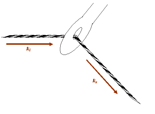
The eye of the needle is, in this analogy, the position of the atom. The question I want to ask is: how am I allowed to move the atom so that the phase relationship between the incident beam and the scattered beam remains constant? This is equivalent to asking: how can I move the needle keeping the thread which extends from the source to the detector taught and of constant length?
Let’s draw the thread and the needle on a larger scale, and more symmetrically, as follows:

The thread is of constant length. The source and the detector are fixed. That means the allowable positions of the needle describe an ellipse, as below:

But of course we are only interested in Fraunhofer diffraction, which means the distances of the needle from the source and the detector are very large. That means we can just concentrate on positions close to the red thread above. Zooming into this, we see that in this symmetrical set up, we can move the needle left or right without changing the length of the thread:
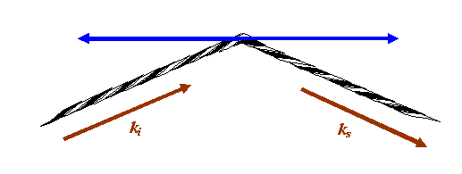
If the eye of the needle moves anywhere along the blue line above, the phase thread remains the same length: any atom or scattering point positioned anywhere on the blue line will give a phase thread that adds with exactly the same phase in the detector plane. In fact, we can move the scattering point out of the paper (computer screen), so the blue line is really a blue plane of points, all of which add in the same phase in the detector plane. The blue plane is called a Bragg plane.
Now let’s rearrange the angles involved so that once again our incident beam is coming from the left of the diagram and is scattering off a diffraction grating.
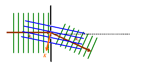
In this rather cluttered picture, the green lines represent points of constant phase in the incident and scattered waves. The dotted black line is a diffraction grating. The dark brown vectors are the k-vectors corresponding to the incident and scattered wave. The blue parallel lines are the planes in which, for any particular phase thread satisfying this particular scattering angle (see above), the position of any actual scattering point in such a plane does not alter the resultant phase of the wave scattered into the Fraunhofer diffraction pattern. I have chosen to draw these lines passing through the gaps in the original diffraction grating. The orange vector is the scattering vector, as defined before. Note that this vector is perpendicular to the blue planes.
In most of textbooks, only the blue and brown lines are drawn, like this:

Furthermore, the picture is usually rotated to look like this:
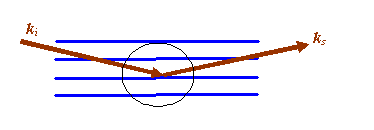
And then if we zoom in to area I have circled, the following geometric construction is made:
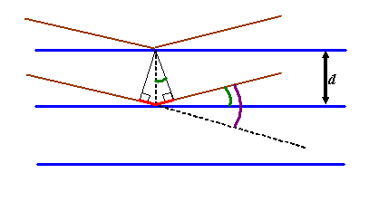
The green angle is called the ‘Bragg angle’ which I will call θB. It is half the total scattering angle which until this point we have called θ (shown coloured purple above). Be warned that in crystallography and most (but not all) contexts in electron microscopy, θ is assumed to be the Bragg angle, the subscript being left out.
We’ve already said that any atom positioned anywhere on a particular blue plane (the planes extend in and out of the paper/computer screen) will scatter into the Fraunhofer plane with the same phase. We now consider the following problem: for a particular separation of adjacent blue planes (Bragg planes), at what scattering angle will atoms positioned in either plane also scatter with identical phase into the Fraunhofer plane?
To work out the answer, we now draw two phase threads, one scattered by the top blue plane, the other scattered by the next blue plane down. For these threads to end up in phase, the extra path length experienced by the lower thread (the red line in the diagram above) must be an integral number of wavelengths long: that is, nλ, where n is integer. From any one of the little right-angle triangles drawn above, we see that this distance is 2d sin θB, where d is the separation of the planes. When this condition is satisfied, all atoms in either plane, or indeed any other plane which is positioned an integral number of distances d away from the first plane (i.e. at 2d, 3d, 4d, etc), will scatter in phase to the diffraction pattern. Clearly, when all the atoms are scattering phase threads which have exactly the same phase in the diffraction plane, then at this particular scattering angle, we get a huge scattered amplitude (intensity peak). Reiterating, strong scattering occurs when

which is the very, very famous Bragg Law. It is justifiably famous, because this very simple little equation launched the whole field of X-ray diffraction, and thereby the study of the solid state. Without it, we would not understand the structure of matter.
However, having said it is a simple equation, it does leave quite a lot of space for misunderstanding and confusion. When I was first taught it, the teacher seemed to imply that is was necessary for the atoms to be periodically arranged along the blue lines. Many texts start by considering a row of equally-spaced atoms and then deriving the fact that only symmetrically reflected waves will be in phase with one another. For a very long time, I really thought Bragg’s Law only applies to planes of atoms which were themselves crystalline. One then begins to wonder how the exact arrangement of atoms in any one (blue) plane affects the reflectivity, or the phase of the reflected waves. All this is very confusing, because the geometric construction above doesn’t say anything about the position of atoms in the blue planes. It seems very artificial to imagine that a plane of atoms reflects radiation like a mirror.
Well, the truth is, the amplitude of the waves reflected from a blue plane is affected by the total scattering strength of all the atoms in the plane, but the phase of the scattered waves is completely independent of where the atoms are actually positioned on the blue planes. In other words, for blue planes that satisfy the Bragg condition, all the following actual arrangement of atoms would give the same intensity at the Bragg scattering angle.
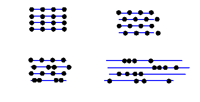
All these Bragg planes have four atoms in them. Of course, in different scattering conditions (different incident and scattered beam directions) the intensity from these very different structures would indeed be different. But in the particular Bragg condition shown, the distribution of the atoms on the Bragg planes does not affect the scattered intensity: in a way, quite a surprising result.
We can think of all this from an alternative point of view via the Fourier integral, which is what we do on the next page…


Copyright J M Rodenburg
| 
