The Fourier transform of a diffraction grating
We’ve already worked out the Fourier transform of diffraction grating on the previous page. On this page, I want to think about it in an alternative way, so that when we come to think of three-dimensional scattering and crystallography, we will have intuitive way of constructing the reciprocal lattice.
When we have an infinitely large one-dimensional grating, of the functional form:
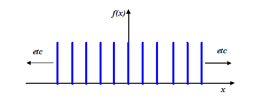
then its Fourier transform is also a one-dimensional series of spikes. If we are thinking of the Fourier transform as the amplitude in the Fraunhofer diffraction pattern, then these spikes are the usual diffraction orders that arise from an optical grating. We call the space of the Fourier domain ‘reciprocal space’. The reason for this is that any prevalent distance, say Δx (such as the distance between atoms or gratings) in ‘real’ space (that is, at the object function which is doing the scattering), expresses itself as a distance 1/Δx in the Fourier domain.
In the case of the diffraction grating, this ‘reciprocal’ relationship is very easy to understand. When the gratings in ‘real space’ get closer and closer, the diffraction orders in ‘reciprocal space’ get wider and wider: that is, they occur at higher and higher scattering angles. It’s easy to understand this physically. The diffraction maxima occur when the path difference between adjacent phase threads, subtending from each grating, is exactly Nλ, where N is an integer. From the usual diagram:
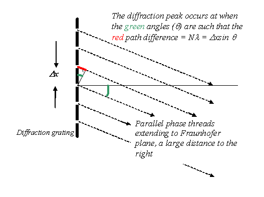
we see that this occurs when Nλ=Δx sin θ, which is the famous diffraction grating equation. Obviously, for constant λ the values of θ where strong interference occurs has to increase if the grating spacing Δx gets smaller. This is the reciprocal relationship between the real space grating spacing and the spacing of peaks in reciprocal space.
Now lets think about doing the Fourier transform of our grating explicitly, using the Fourier transform integral

I’m using the very simplest definition of the Fourier transform so that we don’t get caught up with factors of 2π, minus signs or anything to do with the wavelength. I’ve used a capital K, for reasons which will become clearer later.
Think of this integral as follows. At any particular value of K (proportional, physically, to the scattering angle θ), we calculate the Fourier transform (Fraunhofer diffraction) amplitude by multiplying f(x) by a non-rotating corkscrew function of periodicity K and modulus (radius) of unity, and adding up (integrating) the value of the resulting function over all space. Remember, our corkscrew function is:

but when it is not rotating, ω = 0, and when it has unity modulus, A = 1, we just get left with

which is the kernel of the Fourier integral.
Well, we know exactly what this looks like: remember it is a complex function with real and imaginary parts. For two values of K, one small and one large, it looks like this (where, as usual, we plot the imaginary part as a dotted line).
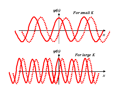
Remember, these are just the ‘shadows’ of a corkscrew projected onto the real and imaginary axes. The solid line is the real axis projection, corresponding to cos Kx, and the dotted line the imaginary projection, i sin Kx.
Now we multiply our grating function, f(x), by these various corkscrews. For a particular small K, we have to multiply the blue and red functions in the following diagram:
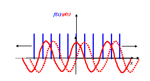
We multiply the two functions point by point, for every point along the x-axis. It’s a bit complicated thinking about what happens for both the real and imaginary parts of this process. In general, we certainly do have to worry about the both components, but for now let’s just consider the real part of the Fourier transform.
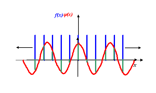
The real part of the Fourier transform will be addition of the lengths of all the green lines above. Because the corkscrew function (the red line) has a modulus (radius) of unity, the product of the red function times the blue function is just the value of the blue function at that point. The product is the green function, which on its own looks like this:
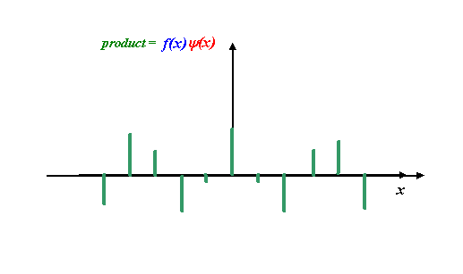
Okay, now can you believe is it reasonable to propose that the integral of this green function (that is, the addition of all the green line heights, taking into account the fact that some of them are negative) is zero? Remember that the diffraction grating function extends infinitely in the +x and –x directions. The important thing to understand is that, for this particular corkscrew function, the real part of the corkscrew (the cosine function) has a different periodicity than the underlying f(x), which in this case is a regular array of spikes. As we add up more and more green spikes (the product of the cosine function with the underlying grating function) then, on average, there will be as many positive green spike values as negative green spike values. Some of these are larger/smaller than others, but because the blue and red functions (in the previous figure) are not ‘in synchrony,’ the cosine function will be sampled at all its positive and negative values at some point over x = +/- infinity (we are assuming the grating is infinitively wide).
In other words, the real part of the Fourier transform of a grating function is zero whenever the corkscrew function (the kernel of the integral) is ‘out of synchrony’ with the grating function itself. However, for the certain special values of K, the exponential eiKx function is synchronised with the grating function. Here are some examples:
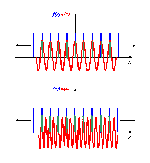
In these exceptional cases, the product (green) function is always positive, and so integral is very large. Remember that what we are doing here is increasing the value of K (the rate of rotation of the corkscrew) and observing the result of the integral of f(x) times the corkscrew function. The integral is zero for all values of K except those where K is equal to N times the periodicity of the gratings. In the above examples, N=1 and N=2. Whenever N is an integer, the positive peaks of the corkscrew function coincide with the grating function. At all other values of K, the product of the two functions oscillate, and so their integrals are zero.
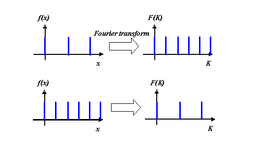
And so we arrive at the Fourier transform. Every time the cosine function fits in an integral multiple of cycles with the real space grating, we get a spike in reciprocal space. It looks identical to original function, except that the spacing of the spikes is proportional to 1/(spacing of spikes in real space).
Two Fourier transform pairs of two different grating spacings scale as follows:
In fact, any periodic object function f(x) will give a series of spikes in its Fourier transform, F(K). The only difference is that the heights of the spikes in the Fourier transform are then of unequal heights. So, for example, the Fourier transform of a series of little ‘top hat’ functions is a series of spikes with amplitudes shown below:

It is one of the astonishing properties of the Fourier transform that the profile of these spikes in reciprocal space (the dotted function in the right hand diagram) is itself the Fourier transform of the shape of the periodic peaks (in this case, the top hat functions) in real space. That means the dotted function is a sinc function, as we derived before. This behaviour follows from the convolution theorem. It is also a way of thinking about the properties of discrete Fourier transforms.
As far as electron microscopy and X-diffraction is concerned, all we need to really understand is that the Fourier transform of an infinite periodic array – say an array of atoms – is a periodic function (a series of diffraction orders). The amplitude of the peaks (diffraction reflections) in reciprocal (scattering angle) space is the Fourier transform of shape of either the atoms (the so-called ‘scattering function’ of the atoms) and/or the cluster of atoms that make up the unit cell (the repeating periodic shape in real space). Within this observation resides most (but not all) of the theory X-ray crystallography and electron diffraction. In reality, we must understand all of this in three-dimensional space.
Some final comments:
1) Of course, if the grating is finite, we end up with residual green spikes (see above) which don’t quite cancel out over the Fourier integral – this gives the little peaks, between the main diffraction orders, which we discussed when we were thinking in terms of the writhing snake.
2) I must emphasise that the writhing snake view of the Fourier integral is identical to one we’ve considered on this page. In the former we consider the addition of little wavefunction vectors in the complex plane, in latter, we emphasise the relationship between the periodic nature of the Fourier transform kernel, and the periodicity of the transformed function.
3) We ignored the imaginary part of the transform on this page. In fact, for a symmetric real function, the sine wave components of Fourier transform always add up to zero, because for every green peak (see above) at x, there is an equal-sized peak of opposite sign at –x, because sine is anti-symmetric. In crystallography, it is usually assumed that for simple crystals there a centre of symmetry at x=0 in real space, so the imaginary parts of reciprocal are lost, although this is not true for an asymmetric unit cell, or a lattice which is displaced by less than one unit cell.
4) The value of ‘K’ in the exponential of the Fourier transform kernel, described above, should not be confused with the value of (small) ‘k’ in the corkscrew function of the phase threads themselves (that is, the electron beams) involved in the scattering process. Because we dealing with monochromatic electrons, all phase threads have the same value of ‘k’. On the contrary, the capital ‘K’ referred to above alludes to lateral wave components of the Fourier transform of the scattering object. In diffraction theory, this is often called ‘K’, to differentiate it from the ‘k’ of the incident and scattered radiation. This will become clearer when we tackle the geometry of the scattering k-vectors involved in diffraction, via the Ewald sphere. In three-dimensions, both k and K become three-component vectors.


Copyright J M Rodenburg
| 
